Saturday, 30 June 2012
Interfacing
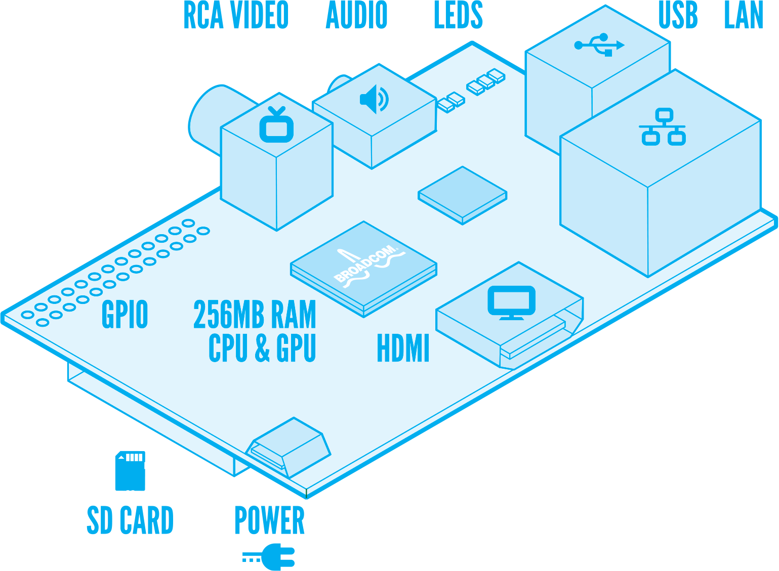
The anatomy of the Raspberry Pi includes a set of general purpose input/output (GPIO) pins which are on the left of the image below. The pins are general purpose insofar as they can be used for anything the user desires, unlike the HDMI, for example, which has a sole specified purpose of carrying video and audio. The GPIOs allow the Raspberry Pi to control electronic circuits by using a library (in Python or C) to send (output) or receive (input) signals through the GPIO header. The Raspberry Pi GPIO is low powered, so will typically require an expansion board to drive higher powered components such as lamps and motors etc.
Because the GPIO is directly controlled through the processor, there is a potential problem of destroying the RPi by making incorrect connections, however, some protection is afforded by using the expansion board.
There are a bunch of starter projects being described on the Raspberry Pi forums which give enough detail to get from beginner (2 years of "electronics" a second level school doesn't count for much twenty years later!) to a working smile circuit. The potential is basically endless, it would be interesting to find some application where the RPi through a web interface could switch on/off, say central heating system; maybe develop this further to email if the temperature is above/below some predefined level. For now, if I could successfully make a traffic light on a breadboard, I'd be happy.
There are probably a lot of things I could/should be doing next week, but the possibility to play with a breadboard, a bunch of resistors and LEDs might take precedence! So Maplin it is on Monday morning...

Subscribe to:
Post Comments (Atom)
No comments:
Post a Comment